5.2 RELEVANT TECHNICAL TERMS
5.2.1 Prior to presenting the information provided to the Inquiry in relation to the investigations into the collapse of the wall at Oxgangs, a brief explanation of some of the key building components that will subsequently be referred to, may prove beneficial to some readers of this Report.
5.2.2 Wall ties are important to the stability of cavity walls in that they are used to tie the inner and outer leaves together, enabling them to act as a single structural element thereby increasing the stiffness of the wall and its resistance to lateral wind-loading. Failure to install wall ties correctly may lead to cracking or collapse of walls.
5.2.3 The requirement for a minimum embedment of 50mm by wall ties into the bed joints of both inner and outer faces of masonry cavity walls was clearly stated in the specification produced by the design team for the PPP1 schools. This requirement is in accordance with both recognised standards within the construction industry at the time and with the guidance that currently applies. For walls with a designed cavity width of 120mm, as in the case of the PPP1 schools, a wall tie with a minimum length of 250mm is required.
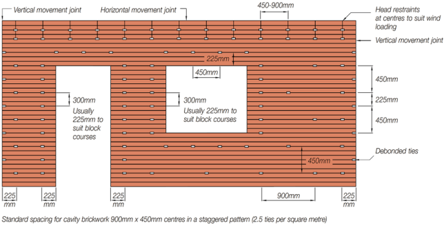
5.2.4 It is also recommended that ties should be evenly distributed over the area of a wall to provide a minimum of 2.5 ties per square metre (900mm horizontal x 450mm vertical centres). Additionally, at vertical edges of openings or at unbonded edges, wall ties should be placed at 300mm centres vertically at a maximum 225mm from the open edge.
5.2.5 Diagram 2 which follows shows the generic arrangement and minimum spacing required for wall ties on a cavity wall including door and window openings.
Diagram 2:
Typical Layout of Wall Ties Indicating Maximum Spacing
5.2.6 A structural engineer designing the structure of a building is required to consider the stability of masonry wall panels to ensure that they can withstand wind-loadings arising from wind-speeds and loadings as currently prescribed in British Standard BS EN 1991-1-4: 2005 for use with PD 6697 2010, (BS 6399 applied at the time of the design of the PPP1 schools). Both standards take account of location, topographical exposure and orientation.
5.2.7 In so doing, a critical element is the size of the masonry panel in terms of its breadth and height. The larger the panel, the greater will be its requirement to be stiffened or restrained by tying it back to core structural elements of the building. The more sides on which a masonry panel is restrained, the greater its resistance to lateral wind-loading, although even if restrained on all four sides, additional reinforcement of the panel may be required to satisfy the mandatory wind-loading requirements.
5.2.8 Structural engineers, having tested the wind resistance of masonry panels through calculations, will therefore frequently be required to incorporate into their design solutions components including wall head restraints, bed joint reinforcement or secondary steelwork such as windposts, to achieve the required structural resistance, particularly in the case of larger panels.
5.2.9 These three types of component can be used either in isolation or in conjunction with each other depending on the customary practice and design intent of the structural engineer responsible for their specification. However, all three may be required for certain size and orientation of panels and geographical locations of buildings. A brief explanation of each of these elements is provided below.
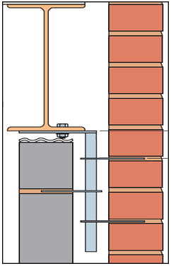
5.2.10 Wall head restraints are used to connect the top of a cavity wall at either intermediate floor or roof level to the structural concrete floors or steel or concrete horizontal beams that are part of the structural frame of the building and run immediately adjacent and parallel to the top of the wall panels. Their installation, usually at around 900mm centres, increases the ability of the panel of masonry to resist wind or other lateral loading. They are built into the mortar joints at the top of brick or blockwork walls and, if it is a steel-framed building, are fixed to the steel beam using either bolted screws fitted into holes drilled in the steel or self-drilling 'Tek' screws. Some contractors still use shot-firing to fix the head restraints to the steel beams but this is no longer viewed as good practice.
5.2.11 Head restraints are normally built into the mortar joints on the inner leaf of cavity walls but versions are also used that are built into both inner and outer leaves. (See Diagram 3 below) This was the type specified for the PPP1 schools.
5.2.12 It should be noted that the absence of head restraints per se is not necessarily a fault as structural analysis may show that they are not required on some narrower horizontal wall panels. However, the strength of wider panels to resist wind loads is dramatically reduced if they are not properly restrained at their head. It is generally easier for design teams to specify them throughout buildings so that there should be no doubt on the part of the bricklayers fitting them as to whether or not to include them in a particular panel.
5.2.13 Lateral restraint fixings are similar to and as important as head restraints in that they are used at regular intervals to tie masonry panels to the vertical columns or stanchions to either side of masonry panels also in order to increase the resistance to wind-loading of the masonry panels.
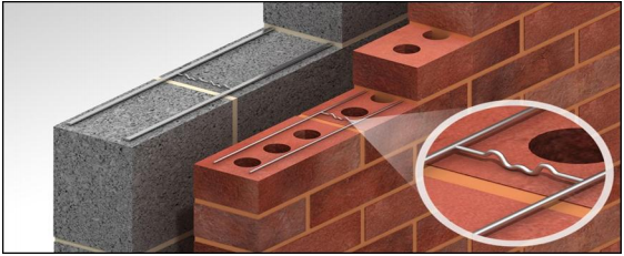
5.2.14 Bed joint reinforcement is used to improve the structural performance of masonry walls by providing additional resistance to lateral loads such as wind. It consists of stainless steel wires, normally two, joined at intervals by welded steel cross-wires to form standard lengths (2 to 3 metres long normally) of a ladder form open steel mesh of a width that is less than that of the brick or block on which it will sit. For a standard 102.5mm wide brick the normal width would be approximately 60mm. These lengths of mesh are placed longitudinally in the mortar bed on top of the brick or block courses at vertical centres as specified by the structural engineer. (See Diagram 3 below)
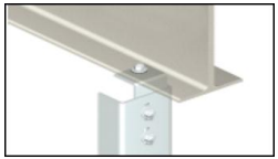
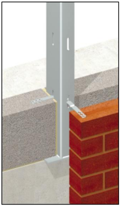
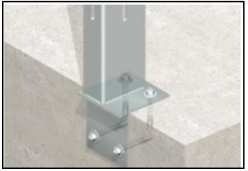
5.2.15 Windposts are designed either to span vertically between floors or between floors and structural beams or to act as vertical cantilevers to provide additional lateral support for otherwise inadequately restrained masonry panels. They can be constructed using a range of different structural steel sections, including channels and angles, to suit different design situations in cavity walls. (See Diagram 4 below)
5.2.16 The design specification for the external cavity wall that collapsed at Oxgangs Primary School was the same specification as that used for most of the external walls throughout the 17 projects constructed under both phases of PPP1.
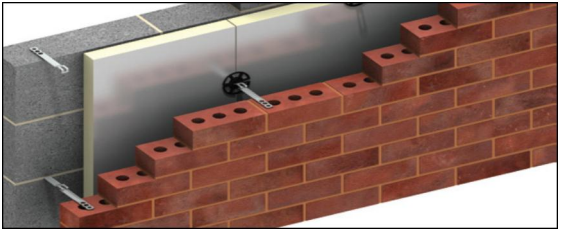
5.2.17 The standardised design for the cavity walls in the PPP1 schools consisted of an internal leaf built of 140mm wide blockwork, a 120mm cavity consisting of 70mm wide insulation slabs clipped to the inner face of the inner blockwork leaf and a 50mm wide air space, and an outer leaf of either 102.5mm wide facing brick or 100mm wide blockwork with a rendered finish. Diagram 3 (below) shows a representation of this type of construction.
Diagram 3: Representation of the standardised design for cavity walls in PPP1 Schools: | |
Above: Example of cavity wall construction including insulation slabs installed in a similar fashion to that specified for the PPP1 schools. | |
Above: Example of bed joint reinforcement similar to that specified for the PPP1 schools. | |
| Left: Example of a head restraint attaching both inner and outer leaves of a cavity wall to a steel beam similar to that specified for the PPP1 schools. |
Diagram 4: Windposts |
|
| Typical connection of windpost to steel beam at head of wall. |
| Typical arrangement for tying inner leaf of blockwork and outer leaf of brickwork to a windpost. |
| Examples of how windposts are connected to concrete slabs at base. |
Diagrams 2, 3 and 4 have been reproduced with the kind permission of Ancon Ltd. | |